It is common knowledge that long distance power transmission lines are operated at very high voltages (on the order of hundreds of kilovolts) to minimise the losses. The argument is: higher voltage → lower current → less loss. Sounds plausible. Let’s dive into it.
First, the voltage-current relationship is a straightforward one:
![\[P=IV\]](https://maytensor.org/wp-content/ql-cache/quicklatex.com-e894bf0b7fdf5d7ba572104cc37d9ca7_l3.png "Rendered by QuickLaTeX.com")
With P for power, I for current and V for voltage. Or rearranged:
![\[I=\dfrac{P}{V}\]](https://maytensor.org/wp-content/ql-cache/quicklatex.com-32eaa3cd4aa3d6ad6fcf4f33df3300d9_l3.png "Rendered by QuickLaTeX.com")
This simple relationship says that for a given amount of power we need to transmit, raising the voltage reduces the current. But on searching the web on this matter, the explanations (even on Stack Exchange) get hazy quickly. In regurgitating what others got wrong a thousand times, the typical reasoning is the following.
First, the power equation from above:
Add Ohm’s law into the mix (R for resistance):
![\[V=IR\]](https://maytensor.org/wp-content/ql-cache/quicklatex.com-beeeef7c697531a36a331e4f0b09437f_l3.png "Rendered by QuickLaTeX.com")
And with substituting the latter into the former, i. e. with replacing V by IR:
![\[P=I \cdot IR = I^2R\]](https://maytensor.org/wp-content/ql-cache/quicklatex.com-f76770077893d9799c839c9f4bb21c5d_l3.png "Rendered by QuickLaTeX.com")
Therefore, power increases with the square of the current, so reducing the current (by increasing voltage) reduces the loss.
At first glance, this sounds absolutely convincing. At second glance, not so. It begins with the fact that the following is also true:
Again, we begin with the power equation:
But now we add Ohm’s law expressed in terms of current:
![\[I=\dfrac{V}{R}\]](https://maytensor.org/wp-content/ql-cache/quicklatex.com-8fc512126075bd42c4ed0a7e73272db3_l3.png "Rendered by QuickLaTeX.com")
Substituting this into the power equation:
![\[P = \dfrac{V}{R} \cdot V = \dfrac{V^2}{R}\]](https://maytensor.org/wp-content/ql-cache/quicklatex.com-cdf5acfe3644cf6f067b098e1a08faf8_l3.png "Rendered by QuickLaTeX.com")
Not only current goes into the power equation with its square, voltage does exactly the same. Apparently, something is not right. Or more bluntly, the common explanations are often simply wrong.
Time for an explanation based on concrete facts and not superficial appearances. The crucial point is to approach the question by looking at the transmission line as a resistive element in its own right (which, in fact, it is). Say, we have a transmission line of 1 km with a resistance of 0.1 Ω per km1. Say, we try to transmit 1 MW of power with by applying a voltage of a measly 400 V. How much power is lost?
First, we calculate how much current is needed to transmit 1 MW of power by way of 400 V:
![\[I = \dfrac{P}{V} = \dfrac{1\,000\,000}{400} = 2\,500 \text{ } A\]](https://maytensor.org/wp-content/ql-cache/quicklatex.com-b05065ca28ccb4115984368a8837bfae_l3.png "Rendered by QuickLaTeX.com")
This is definitely a lot of current. Now all we need is Ohm’s law to calculate the voltage drop across these 1 km of cable with its 0.1 Ω of resistance.
![\[V = IR = 2\,500 \cdot 0.1 = 250 \text{ } V\]](https://maytensor.org/wp-content/ql-cache/quicklatex.com-3ad258239056896a69cd84aceba5e323_l3.png "Rendered by QuickLaTeX.com")
And voltage drop times current is power loss:
![\[P = 250 \cdot 2500 = 625\,000 \text{ } W = 0.625 \text{ } MW\]](https://maytensor.org/wp-content/ql-cache/quicklatex.com-2339ba4deac3924b177266fe31407dff_l3.png "Rendered by QuickLaTeX.com")
With this 400 V setup, the loss would be no less than 62.5 % over only 1 km!
Enter the transformer with which we step up the voltage from 400 V by a factor of e. g. 1000 to 400,000 V. The wire resistance over our test stretch of power line is the same with 0.1 Ω.
![\[I = \dfrac{P}{V} = \dfrac{1\,000\,000}{400\,000} = 2.5 \text{ } A\]](https://maytensor.org/wp-content/ql-cache/quicklatex.com-40376b40d25759ab9e6ffcbf3d07660c_l3.png "Rendered by QuickLaTeX.com")
Voltage up by a factor of 1000 means current down by a factor of 1000. Only 2.5 A are left! This brings the voltage drop down to:
![\[V = IR = 2.5 \cdot 0.1 = 0.25 \text{ } V\]](https://maytensor.org/wp-content/ql-cache/quicklatex.com-f93d6f842ba83e9512d4f24749ac0e6f_l3.png "Rendered by QuickLaTeX.com")
And voltage drop times current is power loss:
![\[P = 0.25 \cdot 2.5 = 0.625 \text{ } W\]](https://maytensor.org/wp-content/ql-cache/quicklatex.com-07b075e47f95d1f4a95c64dcfb244ec6_l3.png "Rendered by QuickLaTeX.com")
Where with 400 V we lost 62.5 % of power, with 400,000 V the loss is cut down to only 0.625 W out of 1 million W (by a factor of 1 million), which is absolutely miniscule by comparison.
The crucial factor is that in terms of voltage we must only consider the voltage drop over the distance of the power line, not the voltage that is applied to it. This means that using
![\[P = I \cdot IR = I^2R\]](https://maytensor.org/wp-content/ql-cache/quicklatex.com-9df5e56636e5397dfb6bfb3e7424da0c_l3.png "Rendered by QuickLaTeX.com")
is definitely correct. But at the same time
is just as right if only we use the voltage drop here (and not the applied voltage). Though this remains invariably unaddressed in pretty much every work-up of the topic.
Further Reading
- Hambley AR. Electrical Engineering. Pearson 2019
Back Matter
Copyright Thomas Gamsjäger
Cite as: Gamsjäger T. High Voltage Transmission Losses. Maytensor 2026
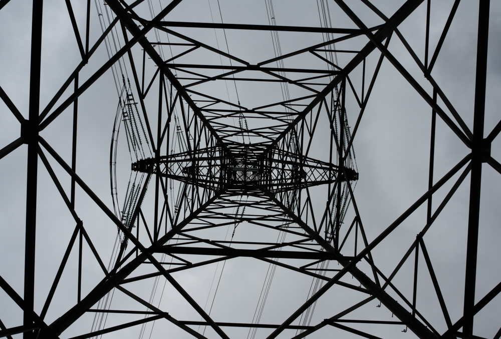
Featured image: A pylon of the newly built 380 kV power line (‘Salzburgleitung‘) in Salzburg, Austria.
Footnotes
- One of the view findable authoritative sources for power line resistance values: https://na.prysmian.com/sites/na.prysmian.com/files/media/documents/TransPowr®%20ACSR%20Bare%20Overhead%20Conductor%20%28Canada%29.pdf ↩︎